In a system with a single X3 Hybrid G4 and a single EVC, the introduction of Datahub for system control is a solution to achieve the Smart Scene function. However, since Datahub and EVC both connect to the same COM port of the inverter , a scheduling conflict occurs, meaning that the inverter cannot establish 485 communication with both Datahub and EVC simultaneously. Therefore, the following are the optimization solutions related to SolaX.
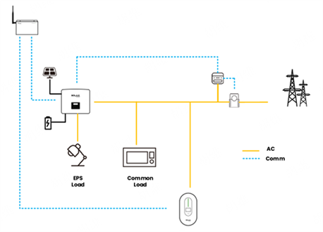
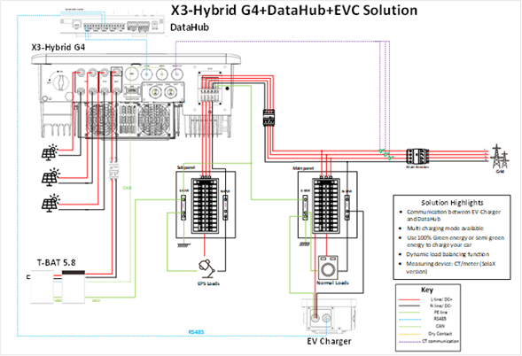
Connect the wiring as shown in the diagram. Connect the inverter to the on-grid side, and connect the EVC as a regular load. Extend a communication cable from the COM port of the inverter and connect it to any RS485 port on the Datahub. Connect the communication cable of the EVC to another RS485 port on the Datahub, and connect the electricity meter's communication cable to the inverter. With this connection method, the DataHub can read the inverter data and forward it to the EVC, or read the EVC data and forward it to the inverter, thereby achieving all the functions that were originally possible when the inverter and EVC were directly connected.
2. Equipment Configuration
After connecting the devices, configuration is required. Also, confirm the specific values of the 485 addresses and baud rates for the inverter and EVC.
2.1 Inverter Configuration (Taking X3 Hybrid G4 as an example)**
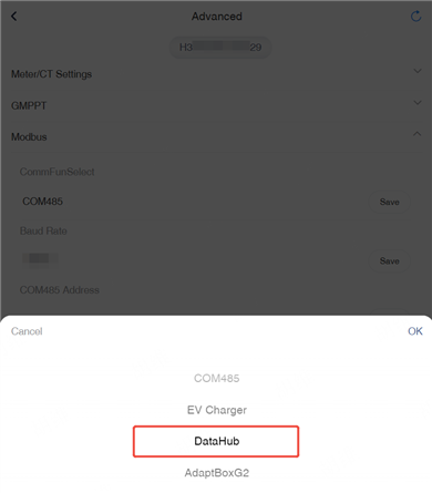
Set the inverter's Function Control to Datahub. The specific configuration path is as follows:
Settings → Advanced → Modbus → Datahub
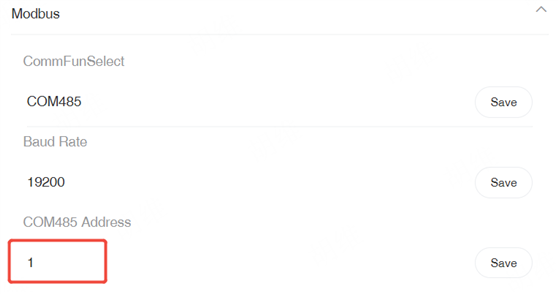
Settings → Advance Setting → Modbus → COM485 Address
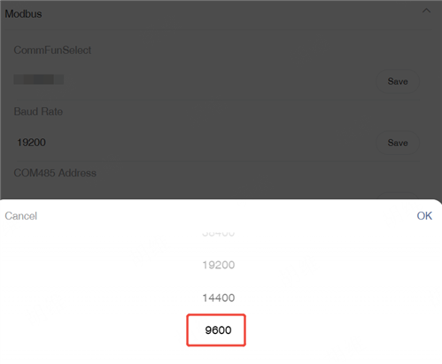
Settings → Advance Setting → Modbus → Baud Rate
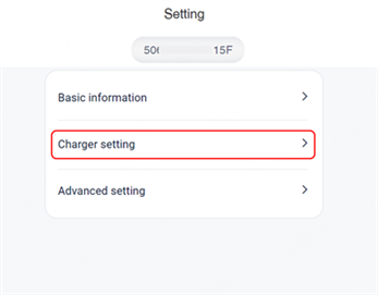
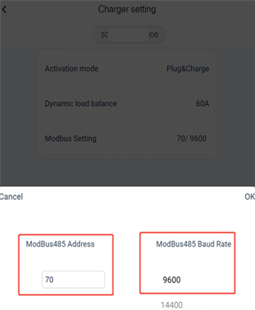
Add the EVC to the power station and configure the network through the Solax Cloud App. After the EVC is successfully online, enter the Remote Setting. After selecting Charger setting, you can find ModBus485 Address and ModBus485 Baud rate inside.
2.3 Datahub Configuration
After the Datahub is online, connect to the Datahub's hotspot and enter 192.168.10.10 for device configuration.
Enter the Serial Port Setting, configure the baud rate for the corresponding devices on the ports, and ensure that it matches the baud rate previously set for the inverter and EVC. After completing the settings, click Save to initiate the recognition process.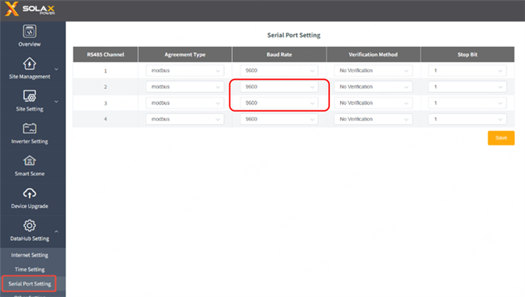
Based on the actual RS485 port connections of the devices, accurately fill in the information for the corresponding devices. For example, if the EVC is connected to the second RS485 port of the Datahub, fill in the EVC's device type, initial address, and number of devices in the corresponding position. If the inverter is connected to the third RS485 port, fill in the inverter's device type, initial address, and number of devices in the position corresponding to the third port. After completing the entries, click the Save button to enable the Datahub to recognize the connected devices.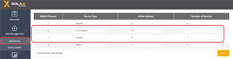
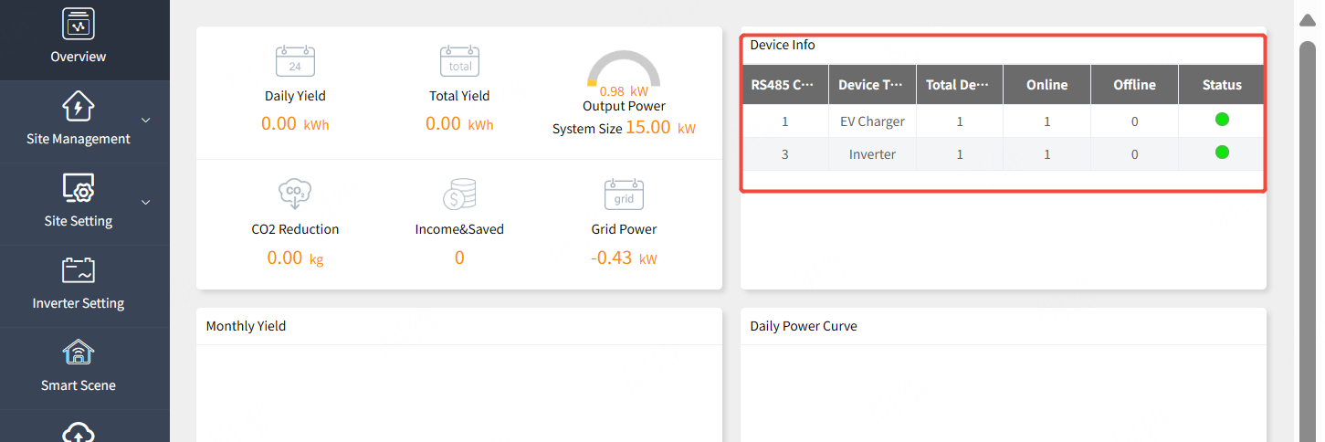
After the equipment is successfully connected, it will be displayed as follows.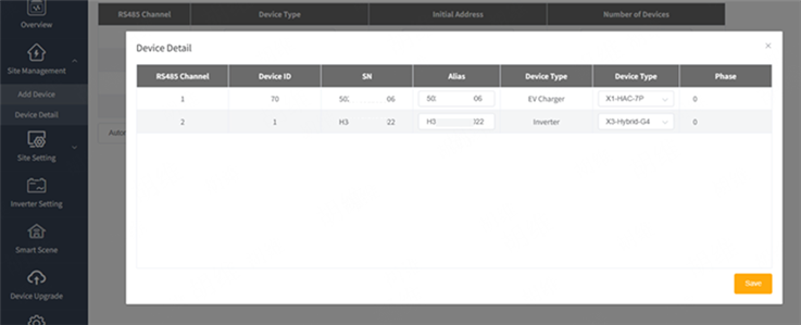
3. Checking and Smart Scene
On the web, you can intuitively and clearly see the online status of the devices, which makes it convenient to confirm whether all the devices in the system are normally connected and functioning.
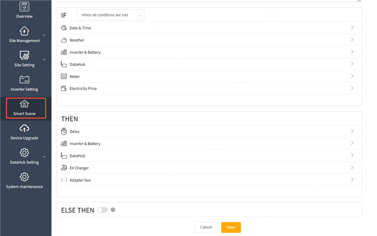
Log in to the local page of Datahub, where you can locate the Smart Scene function and complete the required settings.
The function of automation scenarios is currently only supported on the following models.
|
Inverter
|
EVC
|
Datahub
|
|
X3-Hybrid G4
|
EVC G2
|
Versions V23 and later
|


 Chuck Lee