Section 14a of the German Energy Industry Act (EnWG) requires certain high-consumption devices — specifically EV chargers, battery storage systems, and heat pumps — to be controllable by grid operators in order to maintain grid stability.
To comply with Section 14a EnWG, three control methods are available:
(1) FNN Control Box Direct Control via Dry Contact
(2) Control via third-party HEMS
(3) The FNN Control communicates with the XHUB using the EEBUS protocol, allowing centralized control of devices.
Method 2 refers to the third-party HEMS compatibility list. Method 3 refers to the upcoming XHUB manual. This document focuses on Method 1.
FNN Control Box Direct Control via Dry Contact
In the case of FNN Control Box Direct Control via Dry Contact, grid commands are sent from the FNN Control Box to the controllable consumption device via dry contact; upon receiving the relevant command, each controllable consumption device is limited to a maximum power output of 4.2 kW.
Depending on the devices used and the communication method between them, the function enablement for Section 14a can be divided into the following scenarios.
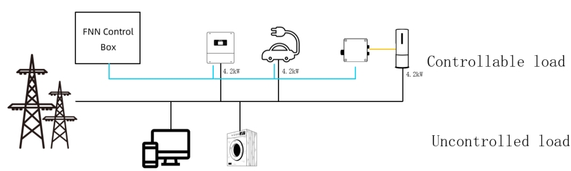
1. FNN Control Box Direct Control via Dry Contact —— The hybrid inverter, EVC, and Heat Pump operate as separate controllable consumption device
When the hybrid inverter, EVC, and Heat Pump operate as separate controllable consumption device, each device is individually regulated by the FNN Control Box in accordance with §14a.
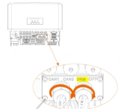
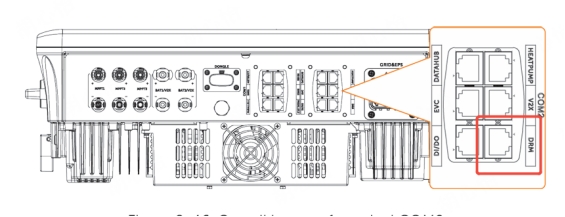
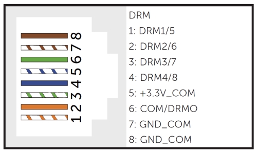
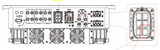
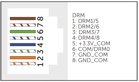
1.1 Dry - contact Communication between hybrid inverter and FNN Control Box
|
Inverter
|
Port
|
Pin
|
|
|
X3
Hybrid
G4
|
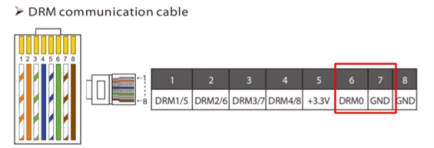
DRM
|
pin6
and
pin7
|
|
|
X3
Hybrid
G4
PRO
|
DRM
|
pin6
and
pin7
|
|
|
X3
ULTRA
|
DRM
|
Pin6
and
pin7
|
|
|
X3
IES
|
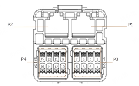
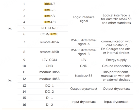
P3 P4
|
pin 6
and
pin 10
|
|
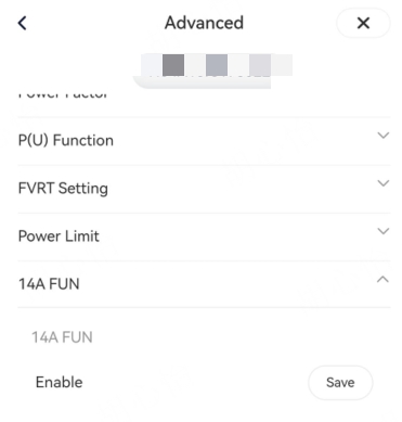
In a single-inverter scenario , the inverter must enable the 14a function. In a hand-in-hand parallel scenario, the master inverter enables this function.
Setting: Advanced Setting→14a FUN
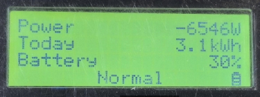
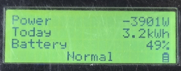
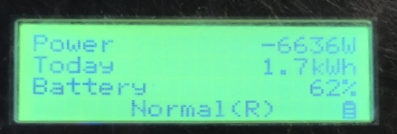
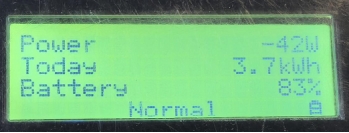
Note: When the FNN Control Box issues a command to limit power to 4.2 kW, the hybrid inverter reduces its power draw from the grid to 4.2 kW.
|
Inverter Power
before receiving the control signal
|
Inverter Power
after receiving the control signal
|
|
|
|
Inverter Compatibility Table
|
Function
|
Inverter
|
Firmware Version
|
|
14a FUN
|
X3-Hybrid-G4
|
DSP≥1.48 ARM≥1.45
|
|
X3-HYB-G4 PRO
|
DSP≥V7 ARM≥V7
|
|
X3-ULTRA
|
DSP≥V18 ARM≥V19
|
|
X3-IES
|
DSP≥V17 ARM≥V13
|
1.2 Dry - contact Communication between EVC and FNN Control Box
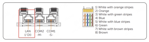
Only EVC G2 equipped with dry contact can establish direct communication with the FNN Control Box via LAN (or DI interface).
Note: EVC G2 comes in different versions—with dry contact functionality and one without. Ensure that the EVC G2 is equipped with dry contact functionality to enable this feature.
|
X1/X3
HAC
|
pin 4
pin 6
pin 8
|
|
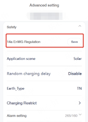
Upon receiving relevant control command, its power output is reduced to 4.2 kW, in compliance with Section 14a EnWG.
In this scenario, EVC must enable 14a function.
Setting: Advanced Setting→14a EnWG Regulation
|
Function
|
EVC
|
Firmware Version
|
Hardware Version
|
|
14a FUN
|
X1/X3 HAC
|
≥V4.04
|
Supports
dry contacts
|
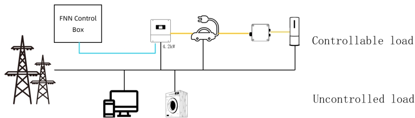
2. Direct control via the FNN Control Box——The hybrid inverter manages the operation of the EVC and the Heat Pump
When the hybrid inverter, EVC, and Heat Pump are integrated into a single controllable consumption device, the hybrid inverter is directly controlled by the FNN Control Box under §14a, and it, in turn, manages the operation of the EVC and the Adapter box.
Upon receiving the relevant control command, the hybrid inverter will execute the following sequence of operations:
(1) Shut down the heat pump via the Adapter box;
(2) Reduce the power output of the EVC;
(3) Reduce hybrid inverter power draw from the grid, which means that when both the hybrid inverter and the EVC need to draw power from the grid simultaneously, the system will first reduce the EVC’s power to prioritize grid power supply to the hybrid inverter.
These steps are carried out in order until the combined power consumption of the hybrid inverter and the EV charger from the grid drops below 4.2 kW.
2.1 Dry - contact Communication between hybrid inverter and FNN Control Box
The hybrid inverter's wiring configuration and function compatibility should refer to the previous scenario 1.1.
2.2 Dry - contact Communication between EVC and FNN Control Box
The hybrid inverter and the EVC communicate in the usual manner, and there is no need to enable the 14a function.
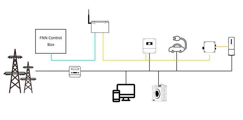
3. Direct control via the FNN Control Box — DataHub controls the hybrid inverter, EVC, and Adapter box.
FNN controls the DataHub via dry contacts, and the DataHub communicates with the hybrid inverter, Adapter box, and EVC.
When the FNN Control Box sends the relevant control signal (0,1), the power at the grid connection point will be regarded as the regulated power and will be limited to below 4.2 kW. When the FNN Control Box sends the relevant control signal (1,1), power import from the grid will be prohibited.
The corresponding control signal is as follows:
|
|
DI1
|
DI2
|
Corresponding Signal
|
Control Command Description
|
|
Signal
|
open
|
open
|
(0,0)
|
No control
|
|
closed
|
open
|
(1,0)
|
Reserved Signal
|
|
open
|
closed
|
(0,1)
|
The grid connection power limit is set below 4.2 kW.
|
|
closed
|
closed
|
(1,1)
|
Prohibit power drawing from the grid
|
1. After receiving the control signal (0,1), the DataHub follows the control logic below:
(1)Reduce the hybrid inverter's power draw from the grid to 0;
(2)Set the heat pump to the lowest gear via the adapter box.
(3)Gradually reduce the power of the EVC until it is turned off;
These steps are carried out in order until the power at the grid connection point drops below 4.2 kW.
|
Inverter Power
before receiving the control signal
|
Inverter Power
after receiving the control signal
|
|
|
|
2. After receiving the control signal (1,1), the inverter, EVC, and heat pump are prohibited from drawing power from the utility grid.
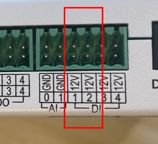
3.1 Dry - contact Communication between Datahub and FNN Control Box
|
datahub
|
Port
|
Silk
|
|
|
DI 1
|
1
|
|
|
12V
|
|
DI 2
|
2
|
|
12V
|
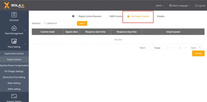
In this scenario, DataHub must enable 14a function.
Setting: Plant Setting→Power Control→14a Power Control
Datahub Compatibility Table
|
Function
|
Type
|
Firmware Version
|
|
14a FUN
|
Datahub
|
≥V2021
|


 Chuck Lee