1.Parallel Application
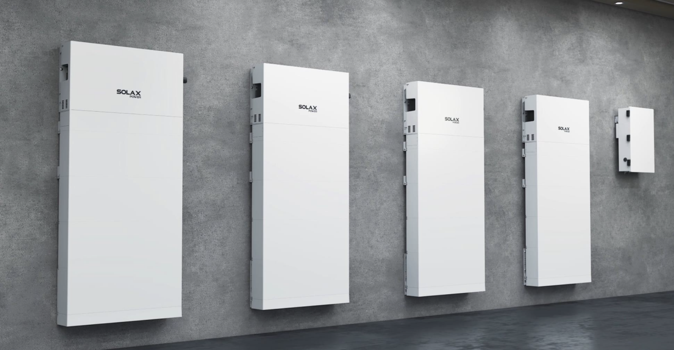
The parallel solution can increase the output power and reliability of a solar power system, enable centralized monitoring and management of multiple inverters, and reduce the cost of the system at the same time. You can start with a small system and expand it gradually as your energy needs grow. This adaptability is particularly useful for residential and commercial users.
1.1 Parallel Requirement
Before operation, please make sure that the inverters meet the following conditions:
|
Type
|
Requirement
|
|
1.Parallel Quantity
|
We support up to 4 inverters parallel
|
|
2.Firmware Version
|
Firmware version should be the same for all parallelled inverters
|
|
3.Rated Power
|
Rated Power should be the same for all parallelled inverters
|
|
4.Battery Quantity
|
Battery quantity for each paralleled inverter should be the same
|
|
5.Parallel Accessory
|
- BI Solution: BI / BI PRO (+Combiner Box)
Note: Combiner Box is needed when paralleling more than 2 inverters.
- Non-BI Solution: Sub Panel is needed
|
1.2 Application Solution
A1-ESS-G2 series inverters support up to 4 parallel connection, unified EMS management function by the primary inverter. The primary and secondary inverters are interconnected via RS485 communication buses. The BI solution diagram shows below.
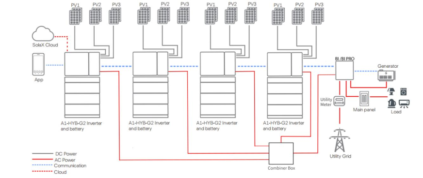
Figure. Parallel Solution(BI & BI PRO)
Customers can also use non-BI solution. The diagram shows below.
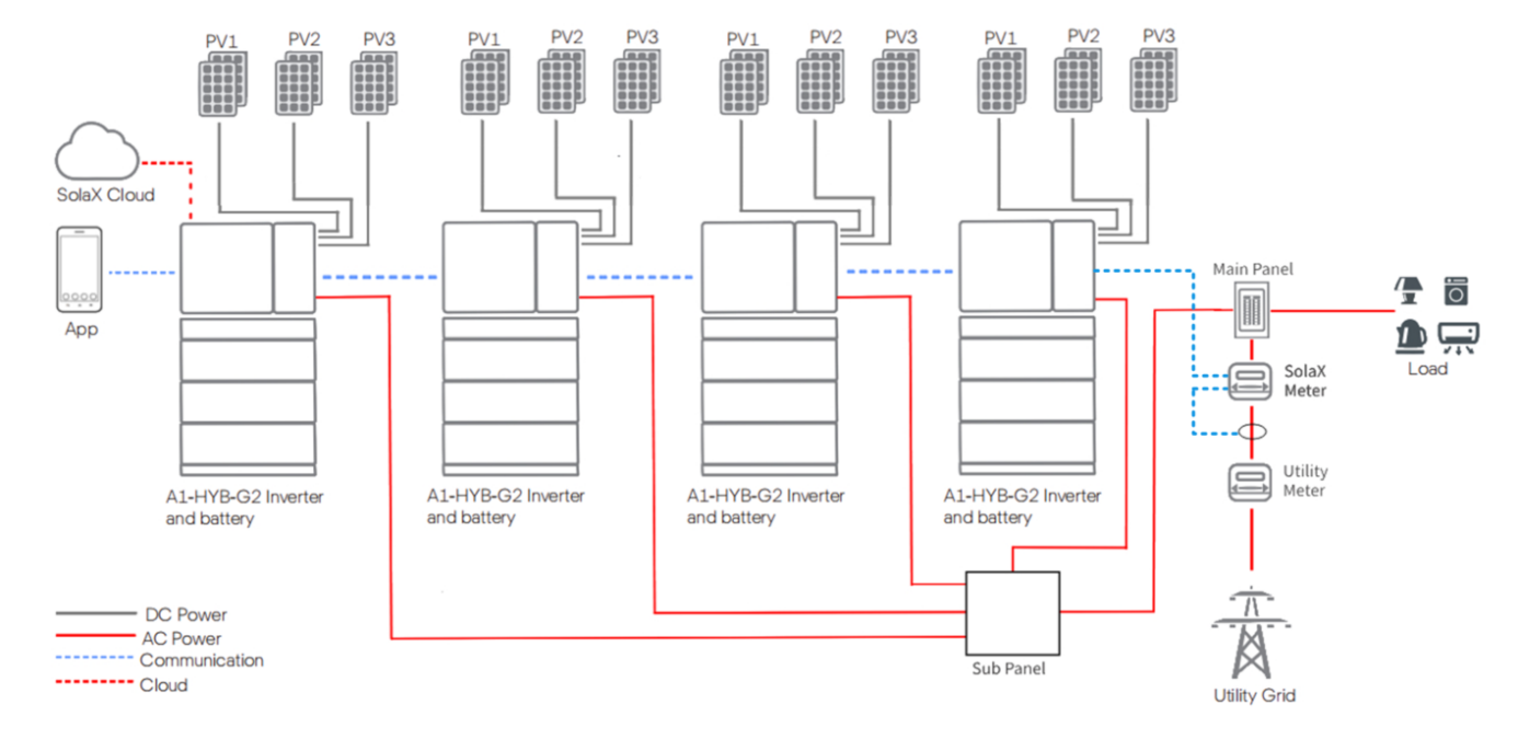
Figure. Parallel Solution(Non BI&BI PRO)
There are 2 types of parallel connection accessories, which is BI or BIPRO for you to choose. The differences are as follows:
Tabel. Comparison for BI and BI PRO
|
Functional Description
|
BI
|
BI PRO
|
|
Drawing
|
|
|
|
Basic
Functions
|
1.Grid on/off switch
2.Whole home loads backup
3.Multiple inverters parallel
4.Microgrid access
5.Generator access
|
1.Grid on/off switch
2.Whole home loads backup
3.Multiple inverters parallel
4.Microgrid access
5.Generator access
|
|
Advanced
Functions
|
/
|
1.Support up to 6-channel smart load
2.Independent access for third-party
grid-connected inverter
3.Independent access for non-backup load which is easy for local wiring
|
2.Parallel Wiring
You can refer to user manual for each unit wiring in details. And check the parallel wiring notes below.
2.1 Power Cable Wiring
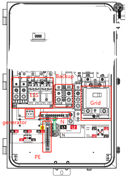
The following diagram shows the power connection between A1-ESS-G2 and BI/BIPRO. You can see that the three corresponding lines on the AC output side of the inverter are L1, L2 and N respectively, which will connect to BI/BIRPO.
Solution 1: When the number of parallel inverter is one or two, which can directly access the BI.
Solution 2:When the number of parallel machines reaches three or four, a combiner box is required.
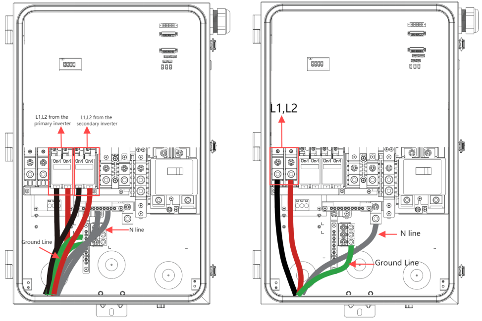
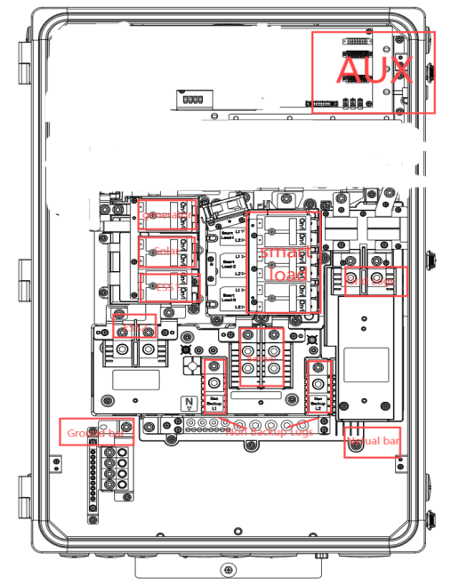
Figure. BI ESS Input from Inverters
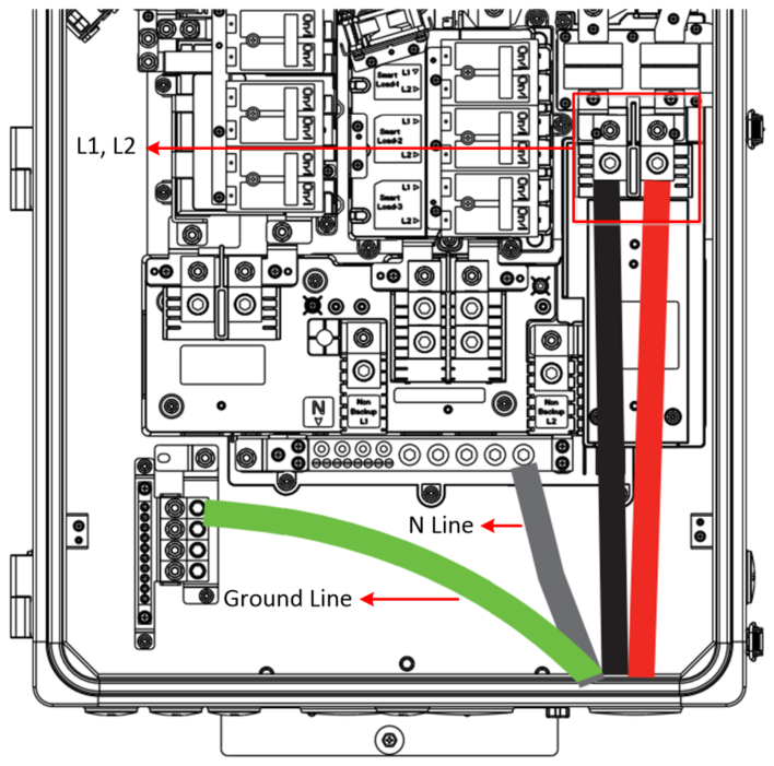
Figure. BIPRO Input from the Inverter
As shown above, each L1 and L2 of the inverter AC output needs to be connected to the corresponding BI interface.
Each L1, L2 of the inverter output needs to be connected to the 'Combiner Box' as shown above.
Then the input from the 'Combiner Box' into the AC side of the BI.(4 inverters parallel solution, need to use the combiner box)
The L1, L2 and N lines from the combiner box need to be connected to the ESS Port of the BI/BIPRO (as shown in the second internal pic).
2.2 Communication Cable Wiring
RS485 communication is used among inverters and BI/BIPRO. The other inverters are defined as seconardy inverters to follow the primary directions.
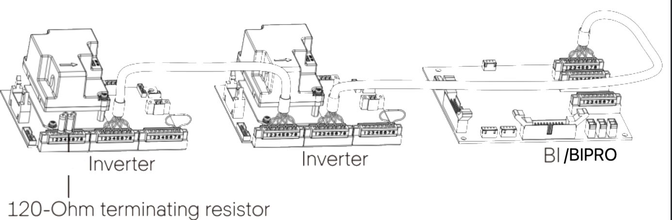
Figure. A1-ESS-G2 Communication Connection Wiring Overview
In the last inverter of the communication chain, a 120 ohm terminal resistor is inserted between the 8-pin female block and the 8-pin male block, which ensures signal transmission quality and stability. It can communicate with up to 4 inverters via communication cables.
The physical diagram of the 120 ohm terminal resistor and the corresponding pinout are as follows.
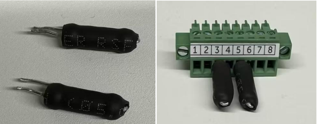
Figure. Detailed Wiring for 120 ohm terminal resistor
The detailed communication connection diagram for inverter and BI/BIPRO is shown as follow.
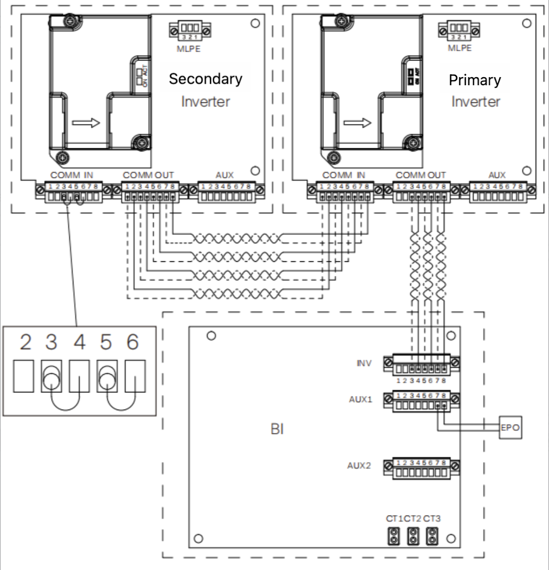
Figure. Detailed Communication Connection Wiring for A1-ESS-G2
Table. Communication Pins Definition
|
Between Inverter and BI
|
COMM Wiring Requirement
|
|
Pin(COMM IN&OUT)
|
Pin Assignment
|
1.The last secondary inverter COMM IN should short circuit 3&4 and 5&6 pins
2.The last secondary inverter COMM OUT should connect all 8 pins to the previous paralleled inverter COMM IN with correct orders.
3.The primary inverter (the one connected to the BI) COMM OUT should only connect pin 3-8 to BI INV pin 3-8.
|
|
Pin 1
|
SYSR_L
|
|
Pin 2
|
SYSR_H
|
|
Pin 3
|
CAN_L
|
|
Pin 4
|
CAN_H
|
|
Pin 5
|
RS485_BI_A
|
|
Pin 6
|
RS485_BI_B
|
|
Pin 7
|
+12V
|
|
Pin 8
|
GND
|
3.Parallel Setting
3.1 App Setting for Parallel Inverters
Each parallel inverter shall be set on App menu. The parallel role and parallel inverter number shall be set on primary inverter, while only the parallel role shall be set on seconardy inverters.
The maximum number of parallel inverters is 4. One of inverters shall be set as Primary, while the others can be set as Secondary1, Secondary2, and Secondary3 regardless of sequences.
Setting path: Menu>Setting>Advance Setting>Parallel Setting
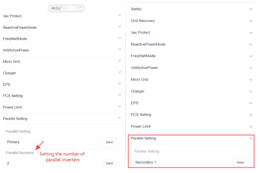
Figure. Parallel Setting for Primary(Left) and Secondary(Right) Inverters
4. Parallel Verification
4.1 Indicator Lights Check
The current LED indicator is defined as follows, using Operation LED 200ms flashing.
Under local conditions, the indicator can be observed to determine the communication status and other statuses.
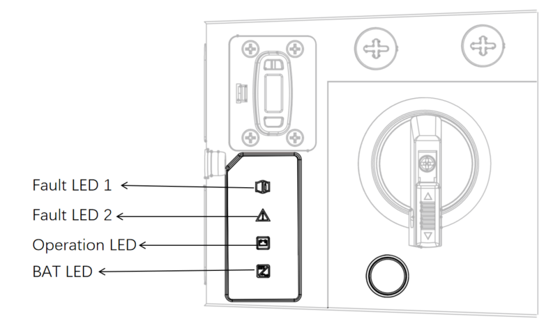
Figure. Inverter Indicator Lights
If all the inveter Operation LED lights are green, it indicates the parallel system is normal operating. When there's red light flashing, please check the fault code on APP or Web and refer to 4.2.
4.2 Fault Code Check
This section contains information and procedures for resolving problems that may occur when paralleling the A1-ESS-G2 inverter and provides you with troubleshooting tips for identifying and resolving most of the problems that may occur when paralleling the A1-ESS-G2 series inverter.
Table. Inverter Paralleling Faults
|
Faults Code
|
Explanation and Solution
|
|
ParallSystem
Fault
|
In the paralleling system, if the primary unit fails, the secondary unit will report this error.
Solution: Check the primary unit's faults and resolve accordingly, or contact after-sales service.
|
|
EPSSyncLost
|
Paralleling synchronization signal fault.
Solution:Check the paralleling line connection, contact Solax after-sales service.
|
|
Parallel
CfgFault
|
Paralleling system configuration error.
Solution:Check if the safety specifications of the primary and secondary units are consistent, the model types (coupled) are consistent, and the rated power is consistent (must be consistent). Continue to check the paralleling role configuration information, set the primary unit's role to
primary, the quantity to the number of paralleling units, and the secondary units' roles to secondary1, secondary2, with no repetition in secondary roles; if there are still issues, contact after-sales service.
|
|
ParalCan
CommsWarn
|
Paralleling communication warning.
Solution:Check the paralleling role configuration information, set the primary unit's role to primary, the quantity to the number of paralleling
units, and the secondary units' roles to secondary1, secondary2, with no repetition in secondary roles; if there are still issues, contact Solax
after-sales service.
|
|
ParallelCAN
ComFault
|
Paralleling CAN communication fault.
Solution:Check the paralleling line connection, contact after-sales service.
|
|
ParallelRS485
ComFault
|
Primary-secondary communication abnormality, incorrect number of paralleling units will cause an error on all units.
Solution:Check the RS485 communication line and interface terminals for normalcy, check if the setting of the number of paralleling units is
correct.
|
4.3 Grid On/Off Switch Check
With the device, you have acquired the system that can be used to power critical loads during a grid outage by using a battery and realize automatic transfer from grid connection mode to off grid mode or from off grid mode to grid connection model by using backup interface (BI). In addition, the inverter also has the ability to use power generated from PV arrays along with other string inverter.
After the parallel operation is completed, try to switch the grid-connected/off-grid status by on/off main breaker, if the switching is successful, the parallel operation is normal.
Note: If you use the Non BI solution, please don't carry on the switch action.


 Chuck Lee
