Product Introduction
TCBox-70 is a battery combiner box independently developed by Solax, which is compatible with HS and HR batteries. It can aggregate multiple battery packs and connect to inverters to expand the battery system.It is easy to operate, convenient to wire, and commonly used in home or small commercial energy storage systems.
By uniting the BMS of multiple battery clusters with the CAN communication port of the inverter, one achieves the master-slave allocation of multiple BMS controllers over the CAN bus.The primary BMS controller is responsible for communication with the inverter, while the slave BMS controllers are governed by the control commands disseminated by the master BMS controller. In order to connect multiple clusters of energy storage battery systems in parallel.
Features
- Enhance the system’s capacity
- Maximum,one may interconnect three battery banks(requiring three BMS)
- Extend the working time of ESS’s
- Ease of cable routing to augment capacity
- Due to the intermittent of triple modules,one may elongate the lifespan of the batteries
Specifications
Table 1 TCBox-70 Specifications
|
Type/model
|
TCBox-70
|
|
Max.operation current[A]
|
70
|
|
Input&Output voltage[V]
|
90-750
|
|
Communication interface
|
RJ45*4
|
|
Max.parallel tower
|
3
|
|
Available charge/discharge temperature range[℃]
|
-30-60
|
|
Storage temperature[℃]
|
-40-80
|
|
Relative humidity[%]
|
4-100(condensing)
|
|
Dimension(W*H*D)[mm]
|
325*231*126
|
|
Weight[kg]
|
2.1
|
|
Installation type
|
Wall mounted
|
|
Protection class
|
IP65
|
|
Cooling type
|
Natural
|
|
Altitude[m]
|
Below 3000
|
TCBox-70 System Schematic Diagram
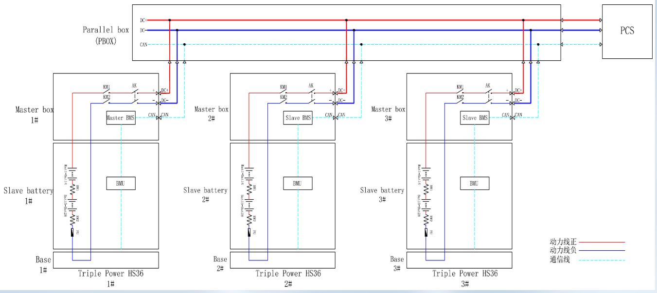
Figure 1 TCBox-70 System Schematic Diagram
System Schematic illustration
- After the system is powered on,the master-slave BMS will be synchronized and allocated;The allocation time is about 30s, and the master-slave BMS is fixed after the allocation is completed, and the master-slave BMS remains unchanged the next time it is powered on.
- The master BMS is responsible for the communication function with the PCS,the update function of the program,and the transmission of system data;
- Communication function and program update function between slave BMS system and master BMS system;
- When the master BMS fails,it will automatically switch(the switch time also 30 s) to another slave BMS for communication with the PCS to ensure the normal operation of the remaining system.
Note: Currently, HS25/HS36 can't differentiate between master and slave BMS for the time being, a battery visualisation project will be done later to display it on the platform
Matching Products
Table 2 TCBox-70 Mating Inverters and Batteries
|
Inverters
|
batteries
|
|
X3-ULTRA
|
HS25/HS36
|
|
X3-G4
|
HR25/HR36
|
|
X1-G4
|
HS51
|
|
X3-G4 PRO(coming soon)
|
|
|
X1-VAST(coming soon)
|
|
Note:
- The number of batteries in each battery set must be the same
- Every battery set must have a BMS
- If there are a large number of stacked batteries,the junction box can be placed under the inverter(single row>9), or on the side of the BMS
- If there are too many sets(3 sets)and the length from BMS to the junction box is not enough, you can choose add a 5-meter long cable as an option.
- Ensure that the wall thickness is not less than 100 millimeters as punching is required.
TCBox-70 Battery Connection Scheme Diagram
Table 3 Battery Connection Scheme Diagram
|
Option/Qty/Type
|
BMS
|
Series Box
|
Inverter
|
|
Option A
|
2
|
0
|
1
|
|
Option B
|
2
|
2
|
1
|
|
Option C
|
3
|
0
|
1
|
|
Option D
|
3
|
3
|
1
|
Option A:
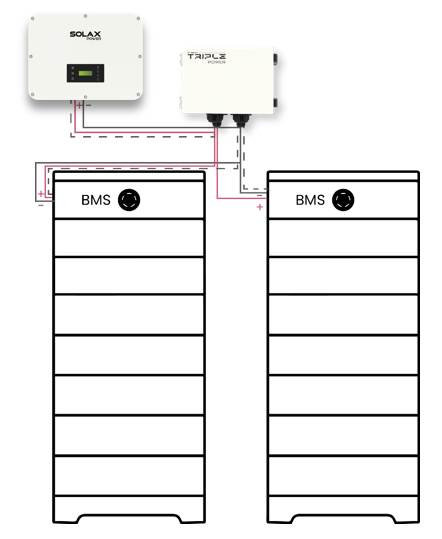
Figure 2 Two BMS(Each cluster less than 9)
Note:When connecting TCBox-70 to the inverter and battery pack, connect the positive and negative poles to TCBox-70 and the battery pack respectively, and connect the communication line through the COM port.
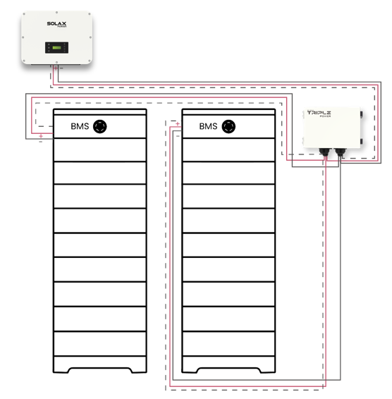
Figure 3 Two BMS(Each cluster more than 9)
Note:To increase the storage capacity of the solar photovoltaic system, we can increase the number of batteries in each cluster of battery packs.
Option B:
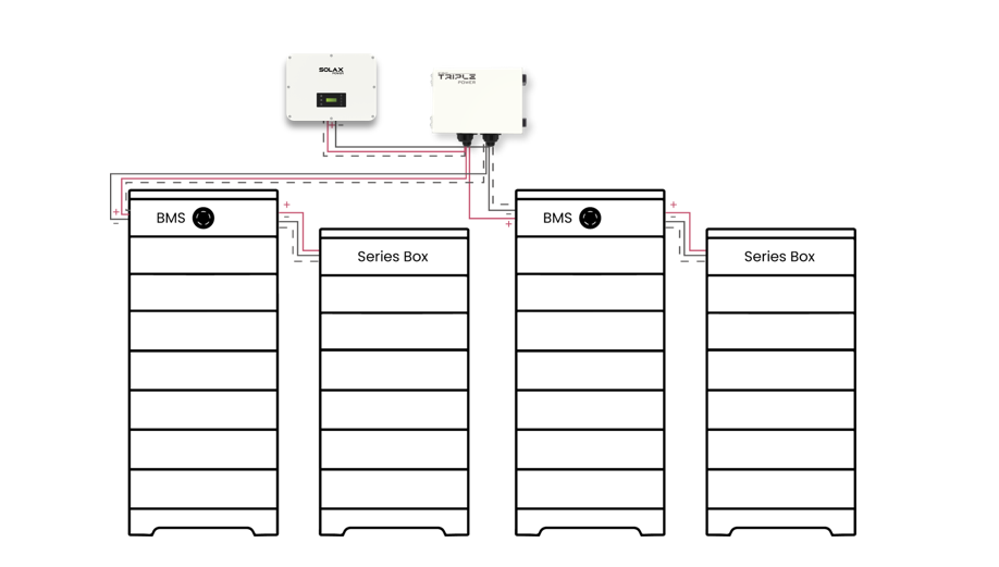
Figure 4 Two BMS+Two Series
Note:The term "SeriesBox" typically refers to a device used to connect battery modules in series. It allows you to connect multiple battery modules in series to increase the system's voltage output while keeping the total current constant. Additionally, the SeriesBox helps prevent the batteries from stacking too high.
Option C:
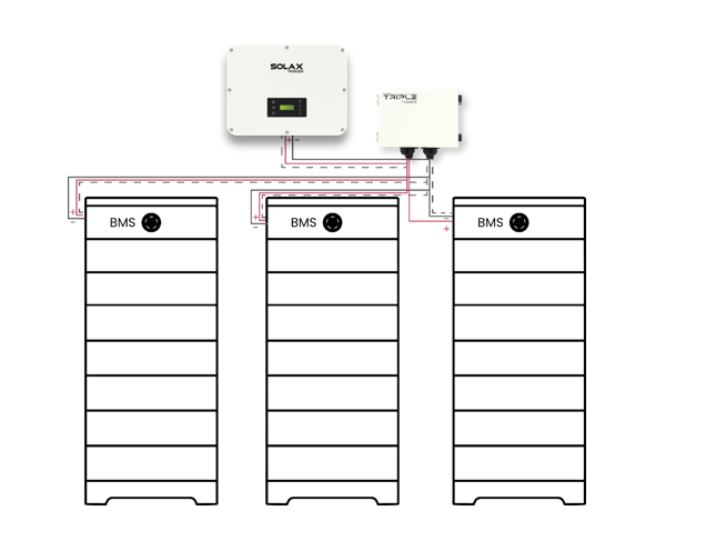
Figure 5 Three BMS(Each cluster less than 9)
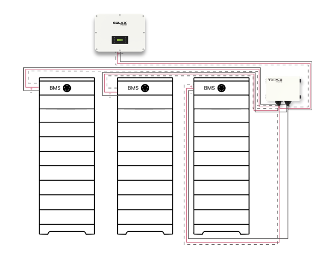
Figure 6 Three BMS(Each cluster more than 9)
Option D:
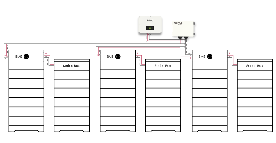
Figure 7 Three BMS+Three Series
Terminals and Wiring
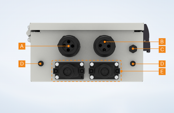
Figure 7 Bottom of TCBox-70
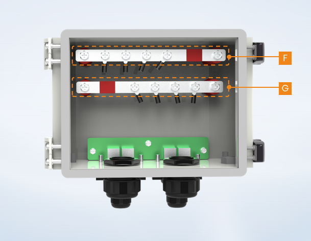
Figure 8 Internal Copper Busbar
Table 4 Terminal Definition
|
item
|
Port
|
Description
|
|
A
|
BAT+ port
|
To pass through positive power cables,for connecting both battery module and inverter,respectively
|
|
B
|
BAT- port
|
To pass through negative power cables,for connecting both battery module and inverter,respectively
|
|
C
|
Breather Valve
|
To balance the pressure differentials inside and outside the Box
|
|
D
|
Grounding Port
|
To connect to the grounding port of both battery module and inverter,respectively
|
|
E
|
COM port
|
To connect to the communication cables,for connecting both inverter and battery module,respectively
|
|
F
|
Terminal block A
|
Only be used to connect positive or negative power cables
|
|
G
|
Terminal block B
|
Only be used to connect positive or negative power cables
|
Compatible Inverter and Battery
Table 5 Compatible Inverter and Battery
|
Inverter
|
Battery
|
|
X3-ULTRA
|
HS25/HS36
|
|
X3-G4
|
HR25/HR36
|
|
X1-G4
|
HS51
|
|
X3-G4 PRO
|
HS25/HS36, HS51, HS50E-D
|
|
X1-VAST
|
HS25/HS36, HS50E-D
|


 Chuck Lee
