Introduction
The Nominal AC output power of X3-Hybrid G4 is restricted to 5.0-15kW, therefore, it can’t be applied to the scenarios where users require more power. Considering this, SolaX provide a solution -- X3-Hybrid parallel solution, which makes it to multiply the power range. In this solution, there are 2 methods to transfer between On-grid & Off-grid status:
- Internal ATS (Up to 3 inverters parallel; External ATS should be set as Disable)
- External ATS through EPS Parallel Box (Up to 10 inverters parallel, but switching time is longer; External ATS should be set as Enable)
Notes: Before operation, please make sure that the inverter meets the following four conditions.
- The software version of all inverters shall be the same;
- The power range of all inverter models shall be the same;
- The type and quantity of batteries connected to all inverters shall be the same, or this function cannot be used.
- X3 Matebox-advanced is not compatible to parallel solution.
Advantages
Robust backup capacity
More energy stored will make user deal with Off-grid situation more leisurely.
Flexible
Greater power range can meet more requirements, and be applied to more scenarios.
Configuration
Cable Connection
It is strongly required that every cable must be connected according to correct line sequence (R-R, S-S, T-T, N-N), otherwise any small misoperation may cause the system running failed. Incorrect line sequence will damage the inverter. To avoid the damage, the default “Disable” has been set to “Enable” in “External ATS” under "Advance Settings".
1. The system X3-EPS Parallel Box G2 (Internal ATS)
Please connect the cables strictly according to diagram below.
Up to 3 inverters can be connected in this solution.
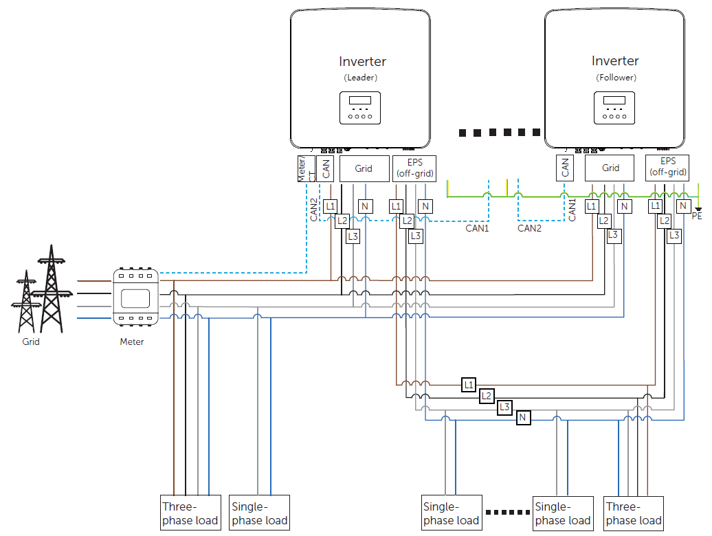
X3-Hybrid G4 Parallel Solution —— Without X3-EPS Parallel Box

2. The system with X3-EPS Parallel Box G2 (External ATS)
Please connect the cables strictly according to Diagram below.
Up to 10 inverters/150kW can be connected with X3-EPS PBOX-150kW-G2;
Up to 6 inverters/60kW can be connected with X3-EPS PBOX-60kW-G2.
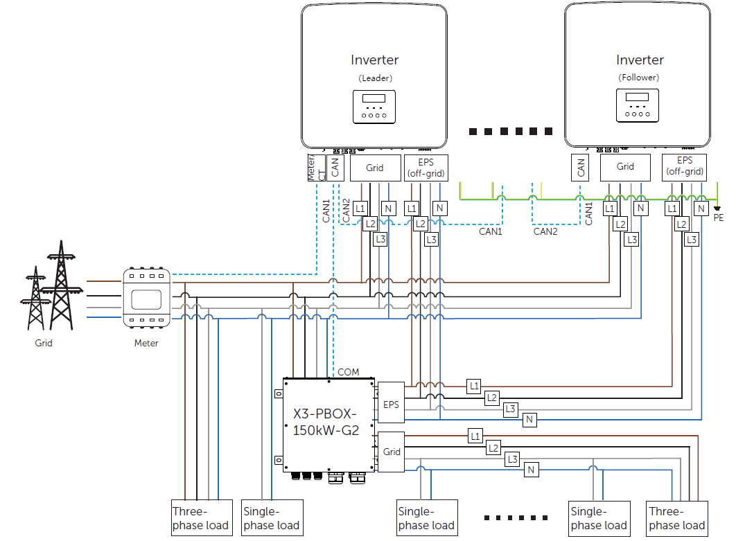
X3-Hybrid G4 Parallel Solution ——With X3-EPS Parallel Box
Power Cable Wiring
1. The system without X3-EPS Parallel Box G2 (Internal ATS)
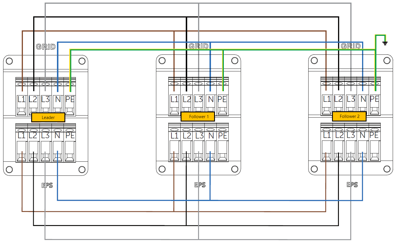
Power Cable Connection —— Without X3-EPS Parallel Box
Note:
- The system requires five-core copper cable for grid connection and four-core copper cable for EPS connection between leader and follower inverter connection.
- leader and follower inverter’s terminal should be connected correspondingly: L1 to L1, L2 to L2, L3 to L3 and N to N. (For both Grid ports and EPS ports connection)
- All PE cable connects to the E-BAR nearby
2. The system with X3-EPS Parallel Box G2 (External ATS)
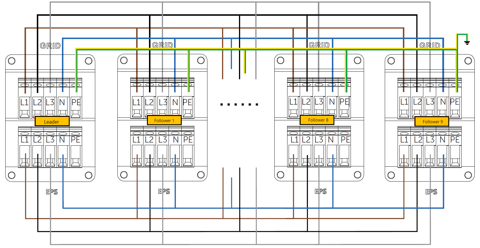
Power Cable Connection —— With X3-EPS Parallel Box
Note:
- The system requires five-core copper cable for grid connection and four-core copper cable for EPS connection between leader and follower inverter connection.
- leader and follower inverter’s terminal should be connected correspondingly: L1 to L1, L2 to L2, L3 to L3 and N to N. (For both Grid ports and EPS ports connection)
- All PE cable connects to the E-BAR nearby
- For X3-EPS PBOX-60kW-G2, it supports up to 6 inverters but the total system power should be below than 60kW. For example, for X3 Hybrid G4 15kW, only 4 inverters can use in this system. For X3-EPS PBOX-150kW-G2, it supports up to 10 inverters.
Communication Cable Wiring
1. The system without X3-EPS Parallel Box G2 (Internal ATS)
Communication Cable Connection —— With X3-EPS Parallel Box
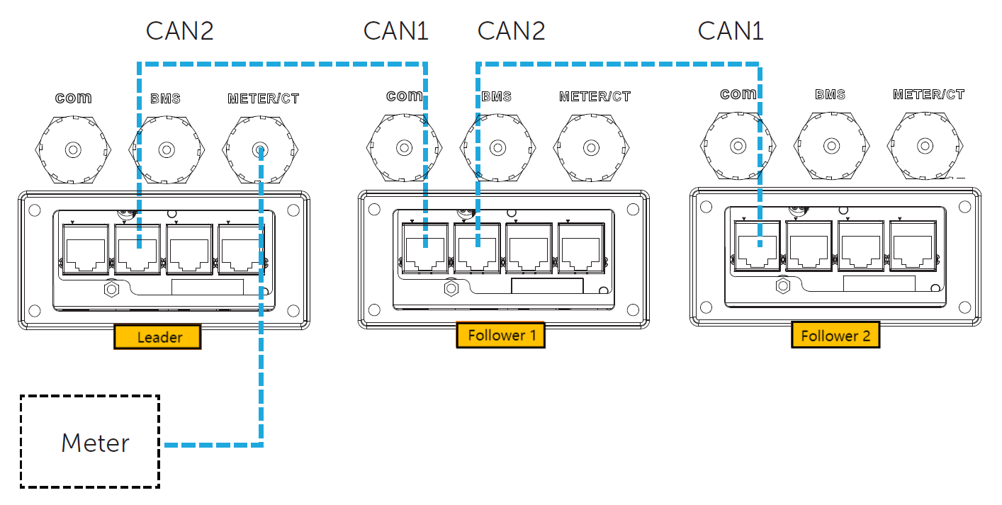
Note:
- Use standard network cables for connection between leader inverter and follower inverter.
- leader CAN2 connects o follower 1 CAN1.
- follower 1 CAN2 connects to follower 2 CAN1; Other inverters are connected in such way.
- Meter connects to Meter/CT terminal of the leader inverter.
2. The system with X3-EPS Parallel Box G2 (External ATS)
Communication Cable Connection —— With X3-EPS Parallel Box
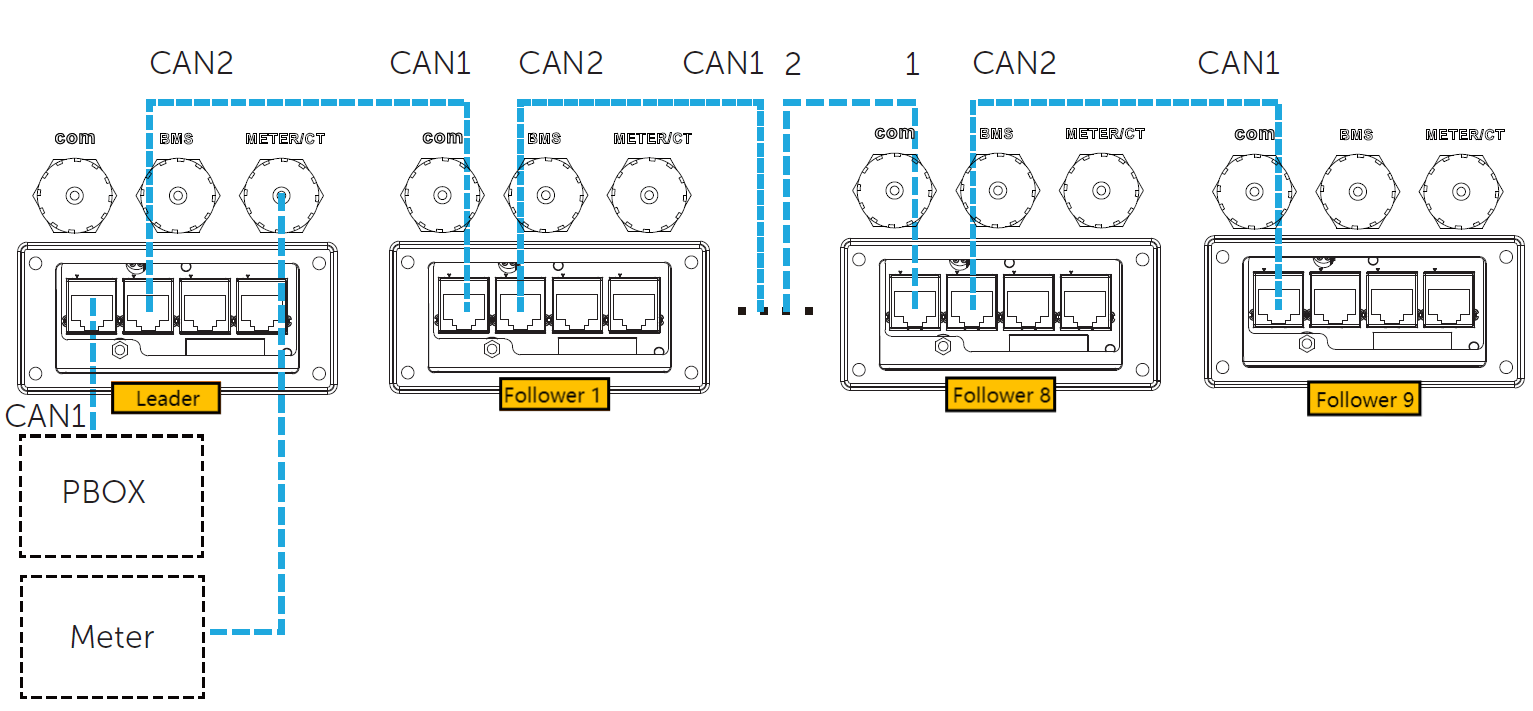
Note:
- Use standard network cables for connection between leader inverter and follower inverter, and leader inverter and X3-EPS Parallel Box respectively.
- leader CAN1 connects to the COM terminal of X3-PBOX device.
- leader CAN2 connects o follower 1 CAN1.
- follower 1 CAN2 connects to follower 2 CAN1; Other inverters are connected in such way.
- Meter connects to Meter/CT terminal of the leader inverter.
3. X3 Hybrid G4 Pin Definition
PIN Definition (CAN1)

PIN Definition (CAN2)

PIN Definition (Meter/CT)

Setting & Commission
1. Parallel Setting
Setting path: Status
Main → Settings → Advance Setting → Parallel Setting → Parallel Setting.

There are 2 settings chosen:
Free
Leader/Master (up to inverter version)
Select leader on the leader inverter (connected to the meter/CT directly), and other inverters will be follower inverters automatically.
Setting path: Resistance Switch
Main → Settings → Advance Setting → Parallel Setting → Resistance Switch

There are 2 settings chosen:
OFF
ON
Select ON on the leader inverter and the last follower inverter in the parallel system.
Note:
If a follower inverter is set to Free mode but not disconnect the network cable, this inverter will return to follower mode automatically.
If a follower inverter is disconnected with leader inverter but not be set to Free mode, this follower inverter will stop working and prompt Parallel Fault.
2. Meter/CT Setting
Setting path:
Main → Settings → Advance Setting → Meter/CT Settings
As for Internal ATS solution, 200A CT (309301004800) is optional.
Please select 200 under Meter/CT Setting → CT Type.

As for External ATS solution with more inverters, a meter with CT is recommended.
Compatibility
Hardware version:
X3-Hybrid/Fit G4.1 X3-Hybrid/Fit G4.2
X3-Hybrid/Fit G4.3 X3-Hybrid/Fit G4.4
Software version:
ARM≥V1.18 DSP≥V1.19


 Chuck Lee
