Introduction
Diesel generators are widely used in areas with unstable grid supply to guarantee a reliable supply in industrial plants, backup systems and off-grid communities. Combined with photovoltaics, these diesel systems offer great potential for long-term cost savings.
The SolaX PV-Genset solution ensures optimum interaction between the photovoltaics and diesel generator, which is available both for on-grid and pure off-grid scene. This saves fuel, lowers energy costs and ensures a stable and reliable power supply.
Please click the mode link to learn the details
|
No.
|
Mode
|
Grid Scene
|
Key Description
|
|
1
|
ATS Control
|
Available
|
1.No communication between DG&Inverter
2.Require external ATS between DG&Grid
|
|
2
|
Dry Contact Control
|
Available
|
1.Inverter controls DG(on/off) with dry contact
2.Require external ATS between DG&Grid
3.DG should support dry contact
communication
|
|
3
|
Generator Always On
|
Not Available
(pure off-grid)
|
1.No communication between DG&Inverter
2.DG is required to be running all the time
3.Not require external ATS
|
|
4
|
Dry Contact Control
|
Not Available
(pure off-grid)
|
1.Inverter controls DG(on/off) with dry contact
2.DG should support dry contact communication
3.Not require external ATS
|
All diagrams are attached in the end. Including parallel system with generator. Please click the link to reach. DIAGRAM
Mode: ATS Control/With Grid
Advantages:
Convenient
Very easy to integrate into existing systems
No extra devices needed (Generator should have its own ATS)
No extra connection needed
Simple control
No complicated setup
In this operating mode, the generator is working as “grid”. The generator do not communicate with the inverter, which means the inverter is unable to control the generator in detail. The ATS (which comes with the generator) will control whether the generator is turned on or off.

Diagram 1
Note 1: A smart meter is required for grid (grid BUS wire), and the communication address should be “2”.
Note 2: A standalone CT is required to anti-backflow and protect the generator. (Standalone CT uses analog signal which is faster than digital signal used in meter, it has the advantage of protecting generator from a feed-in current.);
Note 3: The generator’s rated output power shall be greater than the sum of load power and battery charge power (total or limited, set in the “ExternalGenMaxCharge” Power (0~30000W available, 5000W by default(X3), 3000W by default(X1)).
Mode: Dry Contact Control/With Grid
Advantages:
Eco-friendly
No extra devices needed (Generator should have its own ATS for grid switch, no ATS required when pure off-grid status)
Only need Drycontact connection between inverter&generator
Smart-saving
Various control methods automatically maintain engine status at the most efficient level for all scenarios, resulting in reduced fuel consumption, noise and vibration.
In this operating mode, users can leave the generator to the inverter for smart control with a customized setting. Generally, the inverter will control the generator based on the battery SOC.
For X3-Hybrid-G4&X3-HYB-G4 PRO
Dry contact connection: Inverter COM port (PIN7&PIN8)——Generator(DI)

Note:The rest of the inverter communication pins can be checked in the corresponding manual (Dry Contact section).

Diagram 2
Note 1: A smart meter is required for grid (BUS wire), and the communication address should be “2”
Note 2: A standalone CT is required to anti-backflow and protect the generator (The standalone CT uses analog signal which is faster than digital signal used in meter, it has the advantage of protecting the generator from a feed-in current);
Note 3: The generator should have its own ATS for grid switch.
Note 4: Inverter COM port “Drycontact_out” (PIN7&PIN8).
Note 5:Normal loads that are connected to the grid side (Inverter’s “Grid” port) may lost power during the blackout time, for the reason that the generator may be off based on the generator’s detailed settings.
Note 6: The generator’s rated output power shall be greater than the sum of load power and battery charge power (total or limited, set in the “ExternalGenMaxCharge” Power (0~30000W available, 5000W by default(X3), 3000W by default(X1)).
Mode: Generator always on/Without Grid
It is applied to a pure off-grid scene. In this operating mode, generator is working as a grid. The generator does not communicate with the inverter, which means the inverter is unable to control generator in detail. The inverter will stop output from the “Grid” port, if there is no any voltage source to follow. So the generator should be running all the time to ensure the AC output from the “Grid” port.

Diagram 3
Note 1: Please note that there is no grid and no communication between the inverter and the generator. This case will be applied to a pure off-grid scene when end-user needs normal loads running or all load power is beyond EPS rated power.
Note 2: Normal loads can be connected to “grid” port of the inverter, as generator will be running all the time.
Note 3: A standalone CT is required to anti-backflow and protect the generator (Standalone CT uses analog signal which is faster than digital signal used in meter, which has advantage of protecting generator from a feed-in current);
Note 4:Loads which connected to grid side (Inverter’s “Grid” port) may lost power when generator stop running.
Note 5: The generator’s rated output power shall be greater than the sum of load power and battery charge power (total or limited, set in the “ExternalGenMaxCharge” Power (0~30000W available, 5000W by default(X3), 3000W by default(X1)).
Mode: Dry contact control/Without Grid
It is applied to a pure-off grid scene. In this operating mode, users can leave the generator to the inverter for smart control with a customized setting. Generally, the inverter will control the generator based on the battery SOC.
For X3-Hybrid-G4&X3-HYB-G4 PRO
Dry contact connection: Inverter COM port (PIN7&PIN8)——Generator(DI)
Note:The rest of the inverter communication pins can be checked in the corresponding manual (Dry Contact section).

Diagram 4
Note 1: Please note that there is no grid in this case. This case will be applied to a pure off-grid scene when all loads connect to “EPS” port of the inverter (loads power should be lower than EPS rated power). And there should be no load connected to the “Grid” port of the inverter as it has no power when generator is stopped.
Note 2: A standalone CT is required to anti-backflow and protect the generator (A standalone CT uses analog signal which is faster than digital signal used in meter, it has the advantage of protecting the generator from a feed-in current.);
Note 3: There should be signal connection between inverter and generator in a dry contact way.
Note 4: Inverter COM port “Drycontact_out”(PIN7&PIN8)
Note 5: The generator’s rated output power shall be greater than the sum of load power and battery charge power (total or limited, set in the “ExternalGenMaxCharge” Power (0~30000W available, 5000W by default(X3), 3000W by default(X1)).
Parameters Settings on The Inverter
Setting Parameters Definition
|
Parameter
|
Description
|
|
MaxChargePower
|
The maximum battery charging power from generator. (0~30000, 5000W by default(X3), 3000W by default(X1))
|
|
Reference SOC/Immediately
|
Selecting generator ON/OFF logic by condition a or b:
a: Reference SOC: switch on SOC xx% (20% by default), switch off SOC xx% (95% by default (X3), 80%
by default (X1) ).
b. Immediately: turn on/off the generator when grid status change.
|
|
Switch on/off SOC
|
The inverter will switch on/off the generator when battery reaches this SOC.
|
|
MaxRun Time
|
Maximum operating time of generator. (1000 minutes by default)
|
|
MinRest Time
|
Set the minimum time between generator starting and stopping to avoid a frequent generator’s switching.
|
|
Allow work
|
The time period that allow the generator to work with inverter’s control.
|
|
Char&Disc Period
|
Charging from AC(Generator/Grid) is only allowed during the charging period.
The battery only discharges during the discharging period.
|
|
Charge from Gen→Charge battery to
|
When the battery is charging from the generator, it will stop when the battery SOC reaches the set value. (10%~100%, 10% by default)
|
Settings
With Dry Contact connection
Note: It will be easier to set from Solax APP with online or local mode.
Setting on Inverter LCD
Setting Dry Contact&MaxChargePower

Setting Start Gen Method

Setting MaxRunTime, MinRestTime, Allow Work

Setting Char&Disc period

Setting Char&Disc period2

Setting Charge from grid(Default Charge battery to: 10%, setable range: 10%~100%.)

Setting Via APP
Note: If there is a “save” button for the setting, please click it for every step.


Without dry contact connection
Setting on Inverter LCD
Setting Disable or ATS mode

Setting Char&Disc period(if choose ATS control)

Setting Char&Disc period2(if choose ATS control)

Setting Charge from grid(Default Charge battery to: 10%, setable range: 10%~100%.)

Setting via APP


CT/Meter settings

Compatibility
- X1-IES&X3-IES
- X1-Hybrid-G4&X3-Hybrid-G4
- X1-Fit-G4&X3-Fit-G4
- X1-Vast
- X3-HYB-G4 PRO
- X3-Ultra
Diagram
Diagram 1_DG+Grid_ATS
Diagram 2_DG+Grid_DryContact
Diagram 3_WithoutGrid_DGAlwaysOn
Diagram 4_WithoutGrid_DryContact

Diagram 5_Parallel_DG+Grid_ATS

Diagram 6_Parallel_DG+Grid_DryContact

Diagram 7_Parallel_WithoutGrid_DGAlwaysOn

Diagram 8_Parallel_WithoutGrid_DryContact

Diagram 9_EPS_parallelBox_DG+Grid_ATS

Diagram 10_EPS_parallelBox_DG+Grid_DryContact
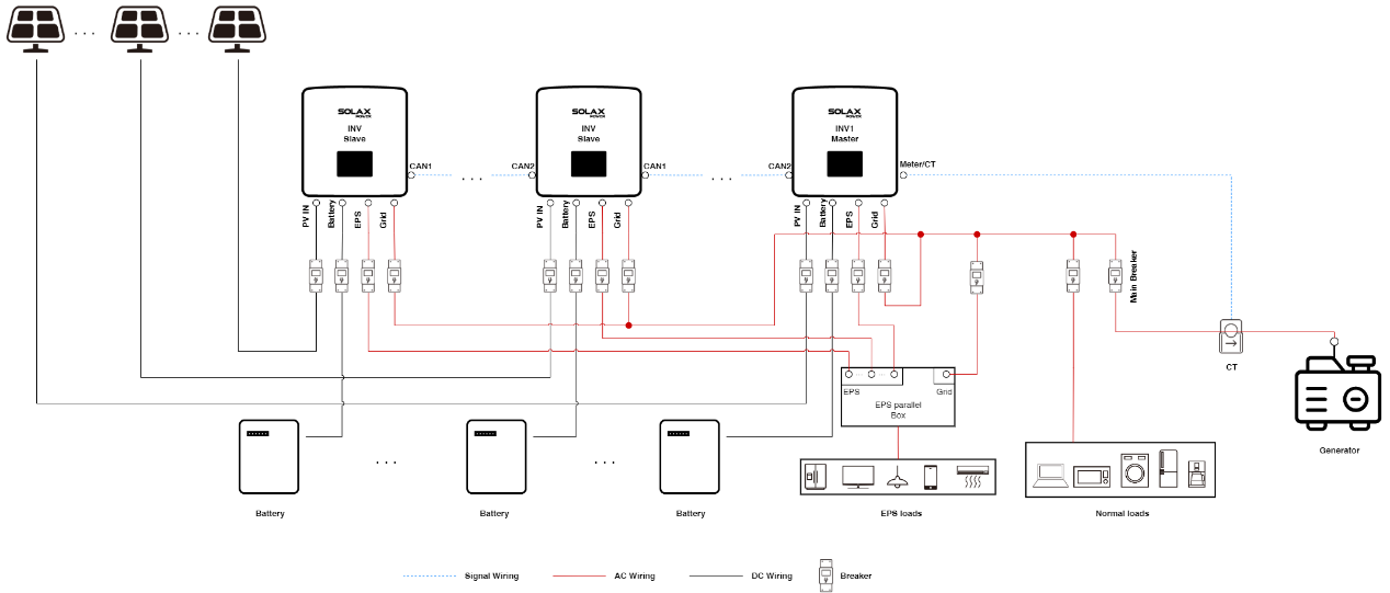
Diagram 11_EPS_parallelBox_WithoutGRID_DGAlwaysOn

Diagram 12_EPS_parallelBox_WithoutGRID_DryContact


 Chuck Lee
