Chuck Lee

FAQ/ Hybrid INV
Issue introduction
The customer doesn't know where to set the export control or the export control fails after the export control has been set.
Confirmation of basic information
[Photo]SN number of the inverter
Meter or CT is from solax.
Guidance for installer
Step1: Set the export control to 0, taking X3-Hybrid-G4 as an example.
Setting path: Setting➡️Advanced ➡️Export control ➡️User value=0

Step2: Check the meter/CT setting. Choose the CT or meter based on actual usage conditions.
Setting Path: Setting➡️Advanced➡️Meter/CT Setting➡️Select

Step3: Refresh the remote setting and re-enter the interface to check whether the value of export control is saved successfully.
Step4: If export control still cannot be achieved after completing the setup, perform the following checks:
Ensure the CT direction is correct.
|
CT only, CT arrow points to the Grid |
Meter with CT, CT arrow points to inverter |
|
|
|


Step5: Enable Installation Check for inspection.
Setting Path:Advanced->Meter/CT Setting->Meter/CT Check->Installation Check


Wait a minute for the results, make the necessary corrections to the table based on the prompt code. Self-check passed will display <Success>.

The error message is just a reminder and may not necessarily correspond to the actual installation issue. If the problem persists after the error is reported, follow the troubleshooting steps outlined later.
Whether the inverter can perform export control depends on whether it can obtain accurate grid connection information. Here, we will explain how to verify whether the inverter has obtained the correct grid connection information when using different sampling devices.
Step1: Turn off all the loads and set the inverter to forced charge mode.
Setting Path: Mode Select➡️Manual➡️Forced Charge
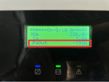
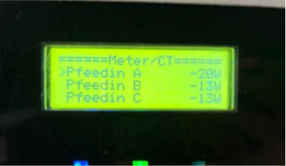
Step2: Check if the power of each phase in “On-grid” is similar to the power in “Meter/CT” in the system status, a difference of less than 100W between the two is considered normal.
|
On-grid status on the inverter Setting Path: System Status➡️ On-grid This information needs to be queried locally through the inverter's screen |
Meter/CT power measured on the inverter Setting Path: System Status➡️ Meter/CT This information needs to be queried locally through the inverter's screen |
|
|
|
|
|
|
|
|
|


- If the power displayed on on-grid status is normal but on meter/CT status is 0, it indicates that the installation of the meter or CT is incorrect, most likely on the load side. Please check the installation location of the meter and re-install it at the grid connection point.
- If the power displayed on both on-grid status and meter/CT status is not 0, but the difference between the two is greater than 100W, check which data is higher.
- If the power displayed on On-grid status is higher, check if there are other inverters or generators connected to the system.
- If the power displayed on Meter/CT status is higher, double-check whether all loads have been disconnected.
Situation1 < When using a CT >
Place the CT clamp on the AC side of the inverter to see if the power displayed in both on-grid status and meter/CT status is the same. Pay attention to the direction of the CT.

If they are not the same, set the CT type in the inverter according to the data on the CT.
|
CT type setting on the inverter Setting Path: Setting➡️Advanced➡️ Meter/CT Setting➡️CT Type |
Check the data on the CT. |
|
|
|


Situation2< When using a Meter-CT >
Place the CT clamp on the AC side of the inverter to ensure that the power displayed in both the on-grid status and meter/CT status is the same. Pay attention to the direction of the CT.

If they are not the same, check the current ratio setting of the meter. The current ratio setting of the meter is based on the current ratio on the label of the CT.
The steps for setting up the meter can refer to the following meter setting diagram or meter manual.

|
The current ratio on the label |
The current ratio setting of the meter |
|
|
|


Step3: If all the measured data above are normal, but export control still fails, then do the following tests: Turn off the DC switch and batteries of the inverter, turn on the loads, then check the power in meter/CT status. if it is under 200W, then the CT or the meter is installed on the AC port of the inverter, instead of the grid connection point.
Information check list
If you have completed the above <Guidance for installer>, and the problem is still not solved, please collect the following troubleshooting information and send them to the Solax technical support team.
1.[Photo]Inverter information including SN and registration numbers.

2.[Photo]Export Control setting values.

3.[Photo]Meter\CT setting.

4.[Photo]CT direction.
|
CT only, CT arrow points to Grid |
Meter with CT, CT arrow points to inverter |
|
|
|


5.[Photo]The inspection results after enabling the "self-checking" function.

6.[Photo] Meter/CT status and on-grid status on the inverter after turning off all the loads and setting the inverter to forced charge mode.
| On-grid status on the inverter | Meter/CT power measured on the inverter |
|
|
|
|
|
|
|
|
|