Background
In order to realize the remote monitoring and control of Hybrid inverters and On-grid inverters, we have introduced the Datahub-Hybrid-On-grid Solution. This solution allows customers to easily integrate hybrid systems onto existing SolaX On-grid inverters or add On-grid inverter systems onto hybrid systems.
The use of Datahub also streamlines the parallel operation of On-grid inverters and Hybrid inverters, making it faster and more convenient. Additionally, for the Datahub+Hybrid+On-grid inverters system, upgrading Datahub and all inverters' firmware to the latest version enables Datahub+Hybrid+On-grid inverters export control, enhancing overall functionality.

Figure 1: Datahub-Hybrid-On-grid Solution Diagram
Solution Highlights
- When the On-grid inverters experiences heavy loads, Hybrid inverters and batteries can supply power to support those loads. When the Hybrid inverters are under heavy load, they can draw power from the grid.
- Support up to 40 on-grid inverters and 10 Hybrid inverters in this system.
- Support export control/ripple control/DRM
- The surplus PV form FTH inverters can charge the batteries.
- The loads will use the energy from FTH in priority to avoid unnecessary discharging
- The FTH inverter in the diagram can also be replaced by X3-PRO G2, X3-MEGA G2
Support List and Connection Limit
Table 1: Supporting List for the System
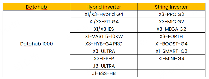
Table 2: Connection Limit for Datahub

Cable Connection
1. Cable Connection – Datahub

Figure 2: Datahub Interface
2. Cable Connection – On-grid inverter
2.1 On-grid inverter Parallel Connection Step:
Step 1: The RS485 in+/RS485 in- of RS485 1 port of the first inverter need to connect to the datahub, the RS485 out+/RS485 out- need connect to the second inverters’ RS485 in+/RS485 in-.

Figure 3: X3-FORTH and X3-MEGA-G2 Communication Port
Note: Communication Port are defined as shown, from bottom to top 1-10, 11-20, 21-30.
Table3: X3-FORTH and X3-MEGA-G2 Communication Port Definition

Step 2: Repeat the connection until all the inverters are connected with RS485.

Figure 4: Datahub 1000 with Forth parallel Connection Diagram
2.2 Datahub-On-grid inverter Connection Step:
Step 1: Remove 8-10mm insulation from cable ends, and then insert the stripped RS485 cable to the 3-PIN plug-in terminal, which is included in the accessory package of the datahub.

Figure 5: RS485 cable Connection Operation Demonstration
Step 2: Plug the terminal to Datahub RS485-1 port. Make sure that RS485+ is connected to DataHub's RS485+, RS485- is connected to DataHub's RS485-, RS485 GND is connected to the GND of DataHub (If there is).
3. Cable Connection – Hybrid inverter
3.1 Hybrid Parallel Connection Step:
Step 1: Make a communication cable, then insert one end of network cable into the first inverter’s CAN2 port and the other end into the next inverter’s CAN1 port and other inverters are connected in such way.

Figure 6: Hybrid CAN port on Hybrid

Figure 7: Hybrid CAN PIN Definition
NOTE: All the CAN PINs will be used for parallel connection
3.2 Datahub-Hybrid inverter Connection Step:
Step 1: Prepare a communication cable, and then make a network cable, insert one end to the master inverter COM port. On the other end find the RS485 PINs.

Figure 8: Hybrid COM port PIN definition

Figure 9: Hybrid COM port Connection Diagram
Step 2: Remove 8-10mm insulation from cable ends, and then insert the stripped RS485 cable to the 3-PIN plug-in terminal, which is included in the accessory package of the datahub.
Step 3: Plug the terminal to Datahub RS485-2 port. Make sure that RS485+ is connected to DataHub's RS485+, RS485- is connected to DataHub's RS485-, RS485 GND is connected to the GND of DataHub (If there is).
4. Datahub-Meter /CT Connection
Note: Only one of the Meter and CT connections can be selected. And the meter/CT should be connected to the master inverter.
By default CT is selected because CT is the most commonly used.
If Meter installed then Meter must be also set in inverters Advanced Settings menu.

Figure 10: METER/CT PIN Definition
Communication wires goes to Meter/CT terminal on:
Meter > pin 4 and 5;
CT-R > pin 1 and 8;
CT-S > pin 2 and 7;
CT-T > pin 3 and 6.

Figure11: CT communication cable
Users can customize the length of the CT communication cable.
The accessory package provides 1*RJ45 and 1*waterproof connector with RJ45 terminals.
When the CT cable is completed, connect the A terminal to the "CT/METER“ port of the inverter and tighten the waterproof screw, and connect the B terminal to the RJ45 coupler.
4.1 Datahub Meter Connection Step:
Step 1: As shown in Figure 1,For The meter On grid connection point, install it on the grid side according to Hybrid Parallel Solution. For The meter between grid connection point and On grid load, install it between common loads and The meter On grid connection point. The AC output of the Hybrid On-grid should be connected between the two meters.
NOTE: The installation positions of the two meters should strictly follow the diagram, otherwise the system may not work properly.
Step 2: For The meter between grid connection point and On grid load, AC wiring should follow what the meter manual instructed.
NOTE: Datahub only supports SolaX CHINT meters
Step 3: For The meter between grid connection point and On grid load Datahub side, connect the RS485 communication. Prepare communication cable. Find the RS485 ports on the meter, connect one end of the RS485 cables to these ports.

Figure 12: RS485 ports on the meter
Step 4: On the other end, Remove 8-10mm insulation from cable ends, and then insert the stripped RS485 cable to the 3-PIN plug-in terminal, which is included in the accessory package of the datahub
Step 5: On the other end, Remove 8-10mm insulation from cable ends, and then insert the stripped RS485 cable to the 3-PIN plug-in terminal, which is included in the accessory package of the datahub.
Step 6: Plug the terminal to Datahub RS485-3 port. Make sure that RS485+ is connected to DataHub's RS485+, RS485- is connected to DataHub's RS485-, RS485 GND is connected to the GND of DataHub (If there is).
Setting and Commissioning
1. Hybrid Setting
Hybrid Setting-Master
Step 1: Find the inverter with meter connected (the master), on the mobile app, go to Setting>Advanced
Step 2: In parallel setting, set the inverter to be “Master”, and then enable “resistance switch” as the picture shows.

Figure 13: Setting Path of “Master”
NOTE: After selecting the inverter connected with meter to master, all the rest inverters will become slaves automatically.
Step 3: On the master inverter, go to meter/CT settings, select the measuring device type, and set meter address(If meter is used.)

Figure 14: Setting Path of Meter
Step 4: On the master inverter, go to Modbus settings, set ComFunSelect to be Datahub, keep the baud rate as default 19200, and set the Modbus address to be 1.

Figure 15: Setting Path of Modbus
Hybrid Setting-Slave
Step 1: Find the last slave inverter, on the mobile app, go to Setting>Advanced
Step 2: In parallel setting, enable “resistance switch” as the picture shows.

Figure 16: Setting Path of Slave
Step 3: For all slave inverters, go to Setting>Advanced>Modbus, set the Modbus address in an ascending order, starting from 2(1 for the master).

Figure17: Setting Path of Modbus address for Slave
2. On grid inverter Setting
Step 1: For all slave inverters, go to the mobile app Setting>Advanced>Communication Parameters, set the Modbus address for every inverter in an ascending order, and set the baud rate as default 9600.
NOTE: There is no master/slave settings for On grid inverters..
3. Datahub Setting
Add device
Login to the datahub, go to site management-add device, select the device type under the serial port, set the starting address and the number of devices under the serial port, and save these settings.

Figure 18: Add Device Setting Schematic
NOTE: Check the baud rate for different inverter models after adding device.
Export Control
Go to site setting-export control, enable the function, select the control mode(total/per phase), feed in buffer(disable/low/mid/high), then select the export power allowed, 0 in this case for 0 export control.

Figure 19: Export Control Setting Schematic
4. Setting Summary
Table 6: Hybrid Setting

Table 7: On-grid Setting

Table 8: Datahub Setting

Installation Tips
- For Datahub+Hybrid+On-grid inverters export control solution, the datahub needs to upgrade to the latest firmware, also keep all the inverter’s firmware to be the latest.
- In this solution the meter connected to the Hybrid inverter On-grid can be replaced by a CT, however the measuring device connected to the Datahub must be a meter.
- Since the Datahub has 4 RS485 ports, so an additional on-grid inverter On-grid can be connected to this solution, and the added on-grid inverter model can be a different one. It does not support another Hybrid inverter On-grid to be added.


 Chuck Lee
